EP9307 System-on-a-chip (CPU)
74HC14 - Hex inverter driving red LED
MIC2774N Power-on reset
Add-On Bus connector
Multi-ICE header (JTAG)
LM1117DT - 1.8v Regulator
JP2 - Boot mode selection "BOOT1" (normal = 2-3)
JP1 - Boot mode selection "BOOT0" (normal = 2-3)
JP6 - Boot width ASDOUT (normal = 1-2)
14.7456 MHz Crystal (for CPU)
MCL7805A - Audio Power Supply Regulator
JP5 - Boot width /CS7 (normal = closed)
Arrow keys and Enter button
Output for CCFL and power supply
K4S561632E- TC/L75 - SDRAM (high 16 bits)
SP/DIF audio output (not mounted)
Headphone output
Microphone input
VITEC Digital audio transfomer (not mounted)
24.576 MHz Crystal (for audio chip)
CS4202 - Audio chip
ADV7123 - VGA Video driver
DB-15 VGA video output
74HCT125 - VGA hsync/vsync amplifiers
LCX16244A - 16 Bit buffer/driver with 3-state outputs (for Ext. LCD)
External LCD panel
LCD panel
LCX16244A - 16 Bit buffer/driver with 3-state outputs (for Ext. LCD)
MT28F640J3RG115 - Flash ROM
K4S561632E- TC/L75 - SDRAM (low 16 bits)
MIC2774N - Reset switch circuitry
DS1337 - Real time clock driver
Reset button
32.768KHz Crystal (for RTC)
CR1225BT1 - Renata litium battery 3V
25MHz Crystal
(for Ethernet chip)
LXT972A -
Ethernet driver
MAX3243 - RS232 Full modem signal amplifier
LM1117MP - 3.3V Regulator
H1102 - Ethernet signal transformer
LM78M05 - 5V 1.5Ah -
Main Power Regulator
Serial port 0 / modem interface
LM78M05 - 5V 1.5Ah - USB Power Regulator
Touch screen header
Power input (7.2V DC, positive center)
Power switch (ON=towards edge of board)
USB port 1
USB port 0
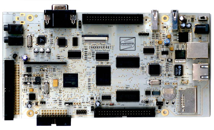
Flying
with the mouse over the image the part numbers and the description of the
various components will appear.
If you click one of the components, its datasheet or pinout description will
open
The
Sim.One is based on the Cirrus Logic EP9307 running at 200Mhz.
The EP9307 contains an ARM920T processor, a MaverickCrunch math coprocessor
and assorted logic and peripherals.
The board has two banks of RAM for total 64MB, and 8MB of fast onboard flash.
Sim.One has many I/O peripherals as you can see in the following connectors
list:
- Add-On Bus Connector
- SD/MMC card socket
- Serial Port 0
/ modem interface
- External LCD Panel
- Ethernet RJ45
- Headphone output
- Microphone input
- Two USB ports
- DB-15 VGA video
output
- Touch screen
- Characters LCD
display
- Arrow keys and
Enter button
For
the pinout of this connectors, you can visit the Hitch-Hiker's
Guide To The Circuit Board.
After an initial prototype with 12 layers, the design has been totally rebuilt
in 6 layers,
this is now at the fourth revision (v1.3), you can get a look at the PCB layout
of each layer in in this PDF,
or if you have a gerber viever, you may download the gerber
package from the Sim.One download
section.
The schematics,
organized in subsections, are available in PDF.
The Bill of Material
is available in PDF, or ODS and XLS editable format.
At this point, you
can go more deeply into the hardware at the technical
documentation page or visit the Software page.